
Fluid Mechanics: Hydraulic Press Design and Analysis
Question
Introduction
There are three main methods of transmitting power: mechanical, electrical and fluid power. Fluid power systems can transmit power more economically over greater distance. The work is accomplished by a pressurised fluid bearing directly on an operating fluid cylinder. A fluid cylinder produces a force resulting in linear motion. The fluid power systems are well suited in many industries because of their many advantages: easy and accuracy of control, multiplication of force, constant force or torque and simplicity, safety and economy
Figure 1 presents a fluid power hydraulic press system. The purpose of this circuit is to control motion of the cylinder. The cylinder must extend, bottom out and hold pressure on the plates for some fixed period of time. During this time, pressure must be maintained in order to maintain the contact pressure between the plates (Figure 1b). The popular applications are bonding two pieces of metal together with an adhesive, holding a mold closed while the material is setting etc.
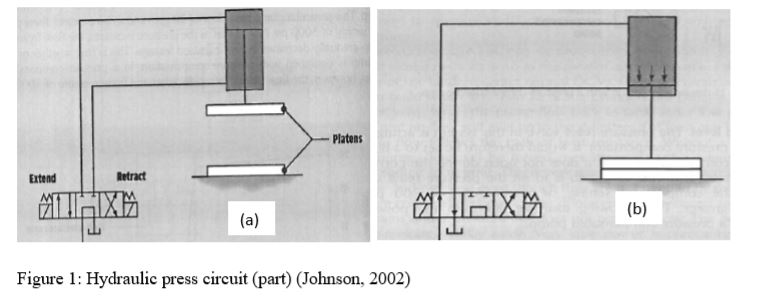
If pressure is to be maintained, the directional control valve (DVC) must be left in the extended position even after the cylinder is fully extended (Figure 1b). Whenever the cylinder is bottomed out, flow of oil is going over the pressure relief valve. This is wastage of fluid power. This study should focus on how to manage the wastage of fluid power. This can be achieved through inserting additional parts in the fluid circuit diagram.
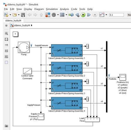
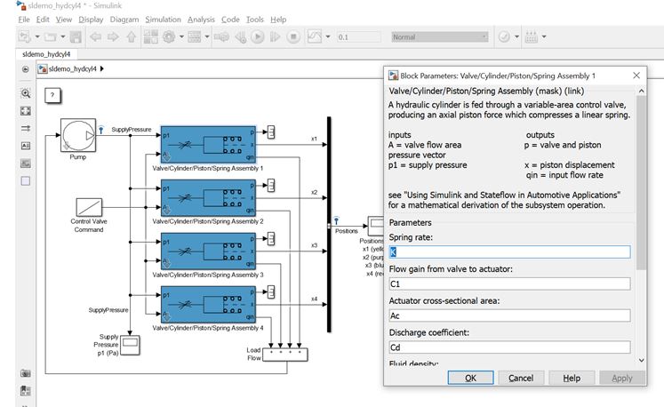
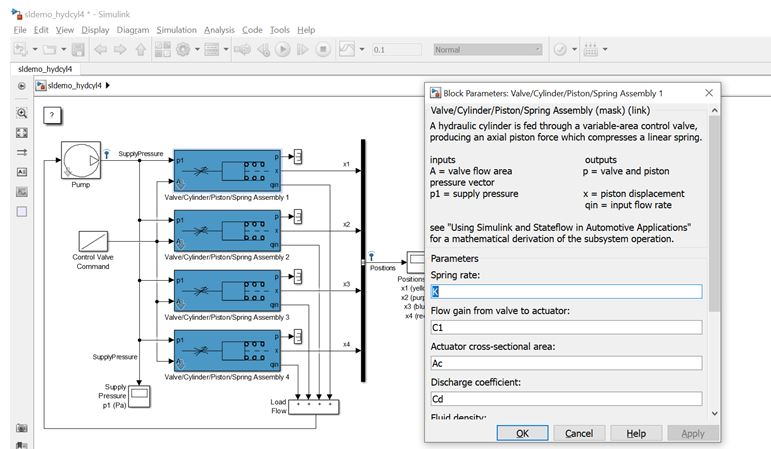
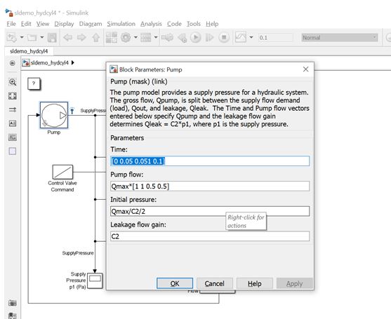
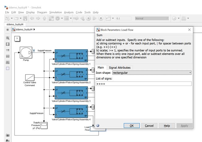
Simulation of a hydraulic circuit in Matlab is a good way to study and analyse the hydraulic circuits you design. In Matlab, you have to use SimScape (Simhydraulic). You have to go to Fluids, then Hydraulics (isothermal). From the library menu, you can draw the circuit. This menu has various components needed to construct a fluid circuit diagram. By choosing the right components, the hydraulic symbols are assembled for analysis.
Your submission should have the following items and headings:
- Introduction to fluid power systems relating to hydraulic press systems
- Literature review on Conventional hydraulic press systems using standard papers from journals, conferences, books and reports
- Working principles of existing hydraulic press systems.
- Develop a case based on your research and develop a set of assumptions for your proposed design (operating pressure can be about 170 bars for example)
- Design and analysis of a new or modified hydraulic press system that gives better control: flow control, pressure control and directional control using sufficient minimum controlling devices and valves
- Safety check of pipes and pressure cylinders (thick-walled or thin-walled analysis)
- Prepare an Excel calculation sheet to put input data, standard equations, creating plots to compare
- Health and safety practices required for maintaining the system.
- Use proper drafting tools to show changes in your new design.
- Draw necessary fluid circuit diagrams
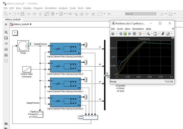
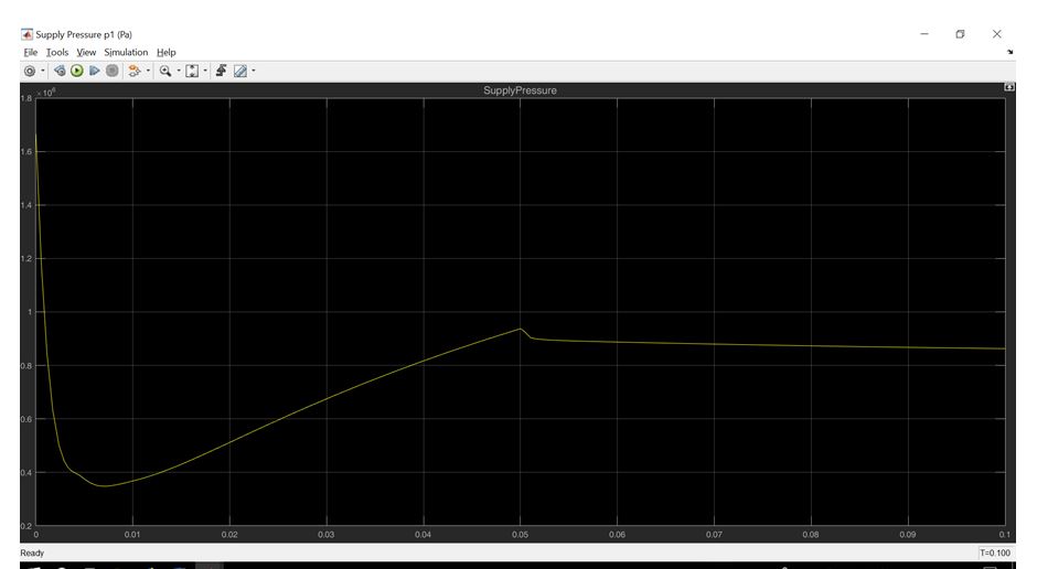
- Apply SimScape and carry out analysis of your new design: piston positions, velocity, flow rate etc. vs time.
Answer
Introduction: A hydraulic press creates a compressive force with the help of a hydraulic cylinder. The way it works is that it makes use of the mechanism which is quite close to the way a mechanical lever works. There was a time when the hydraulic press was also known as the Bramah Press as the person who invented the hydraulic press shared the name. His name was Joseph Bramah and he hailed from England. He was the one to whom the patent had been issued for the development of this technology. The way he came about this was that he had studied the way the fluids have motion and the information he gathered from his observations he put into use in the development of the hydraulic press. He is also known for his contribution in the installation of toilets.
The basic principle with which the hydraulic presses work is that the pressure of a fluid in a system which is closed is constant throughout. This principal is known as the Pascal's Principal. The whole system can be divided into many parts:
- One section of the system is one where a piston acts as the pump. Here the mechanical force which acts upon the object is modest and works with the piston on a broader area. This is responsible for the creation of a mechanical force which is large and is in correspondence with it.
- There is also a tubing of a lesser measure (diameter) which helps in the separation of the press cylinder and the pump.
What is the Pascal's Law?
It is, that when a fluid is contained in a confined space, the pressure it has on the space is transferred with the same energy and same force and has its effect on the area with force which is equal and at a degree of 90 at the walls of the container that it is in. The force that is put on the small piston is then transferred to the larger one and creates motion.
The use of the hydraulic press is mostly done in the works of moldings, deep drawling, forging, processes which are related to metal formation, clinching, and such processes. If you look at the Fermat's Room. It is based on a concept which is quite similar to the way a hydraulic press functions.
There is the use of a plate or a bed in the structure of a hydraulic press. Here the material which is metallic is placed in a way where it can be easily molded, or the shape may be changed, it may be crushed according to the need. The basis of a hydraulic press, as already discussed, is that of the Pascal's law and therefore, the way it works is quite same to the way a hydraulic system works. The main components of a hydraulic press are those of the ones on the hydraulic system, which include the following:
- Pistons
- Cylinder
- Pipes
And so on.
The functioning of the hydraulic press is not very complicated. The cylinders that a hydraulic press has, which are two are poured into with the fluid. This fluid is usually an oil, and the cylinder is known as the slave cylinder. The way it works is that the piston here is applied force on and pushed which in turn compresses the fluid that is in the pipe and it moves into the larger cylinder. This larger cylinder is one that is called the master cylinder. The motion makes the larger cylinder's piston apply force and push the fluid back into the slave cylinder which is the original one. The smaller cylinder applies force on the fluid which turns into a force which is greater when the fluid is pushed din to the larger cylinder which is the master cylinder. The use of a hydraulic press in usually in the field of industries, as there is often need for larger application of pressure for the purpose of changing and compressing metal shapes in the form of sheets and such. For this purpose, a hydraulic press in an industry is used along with press plates.
The hydraulic press is used in the industrial areas. The most prominent function of a hydraulic press is that of pressing metal into thin sheets with the application of a large amount of pressure. It is also used in processes such as glass thinning, in the cosmetic industry where there is need to manufacture powder and so on. Some of the uses of the hydraulic pumps are also, in the area of making swords. Here the technology is used for the flattening of the material, which is raw steel, into the shape of a sword. It is also used when a car needs to be crushed. The pressure that is applied on the plates of the press makes the application of the large amount of pressure on the cars which is necessary to crush it, easier. A third field where it may be used is at the industry of making powders. One such example is the making of cocoa powder. In the process of its manufacture, the beans of cocoa are crushed, and the liquid known as chocolate liquor is extracted from it. The use of a hydraulic press is done for this process and the liquid is then used to make powder and this is a fat free powder which is made.
The hydraulic press can be of various kinds. This categorization depends on the kind of usage it is needed for and the type of industry. Following are some of the types of hydraulic presses:
- One type is the laminating press. This is one category of press where the operations are not done automatically. This is not true for the other kinds. Here, there is application of manual operation for the functions to be completed. Here the press consists of two different plates which are basically openings. These two openings help in the heating and cooling processes where one helps in the heating and the other helps in the cooling process. This helps in speeding up the process of lamination. The use of electricity is done, or that of oil for the purpose of heating the plates of the press. The uses of the press is when there is need to laminate documents, covers of books, cards, and so on. The laminating press is used not only for domestic but also in the industrial fields.
- Another kind of a hydraulic press is the arbor press. These presses are those which are not used in the heavy-duty processes. They have further varieties and the size of various such presses also differs. Although, what you can call a drawback is that, these may not necessarily be able to compress very large material and may therefore not be able to apply large amounts of pressure. These may usually be used on the processes such as, stamping, making holes, tearing material and so on.
- A third type of presses the power press. A power press is one which are used in industries where there is need to work with large amounts of material. Here heavy equipment and machinery is used. There presses are also divided into types. There are two different types of power press. This division of kind is based on the type of the clutch which is being used in the press. The two kinds of press are part and full revolution press based on the clutch. The revolution category, unless the full revolution is done by the crankshaft, the disruption of the clutch cannot be done. The other kind, is different. Here the disruption may be done at any given time. This may be after the revolution is complete or even before it. The power press are not safe presses as they are usually used for large amounts of work and are done with heavy materials and objects. While making use of a power press, it is therefore essential to make use of appropriate safety measure.
- C- frame presses are those which are shaped in the manner of the letter "C". These are shaped in this manner so as to increase the mobility of the workers at the machine by freeing up floor space of the area. This is also a kind of press which does not have the facility for multiple processes, it offers only a single facility. It helps in the work of assembling material, along with functions such as drawing, or straightening material. Not only this, the C- frame presses offer along with these other facilities which are its extra facilities and features, like pressure gauges, or like wheel stands and more.
- The next kind of press is the pneumatic press. These are the ones that are basic level hydraulic machines as they function by making the air compressed which leads to the movement required. The work done by this kind of press s quick. Although it has disadvantages as well, where it cannot create very high amounts of pressure. This is possible in hydraulic systems other than the pneumatic one. The pneumatic hydraulic systems are helpful in the break systems of vehicles like cars and even in aircraft systems. It is also used in industries and play the role of punching, drawing, and so forth. There is also need to apply a number of safety measure with the use of this system, as there is need for an operator to constantly work on the machine.
- The last two systems are the H-frame presses and the Assembly presses. These are such that the first one can easily handle multiple applications at a time and is also known for its shape looks like an “H”. The second one on the other hand is one which is capable of the creation of very high amounts of pressure with the help of hydraulic fluids and also pistons. These help in the maintenance and the assembly of the parts of the system.
It must be pointed out that hydraulic system often require the application of measures of safety for the operators. Especially as some of the systems are those which need to be operated in a manual manner and are not automatic like the rest of the systems. They need to be careful with the system and the application of various safety measure is essential like the electricity safety measure.
Hydraulic presses offer a number of benefits in the field of industries. They help in the compression of materials till the highest possible limit. They also have lesser diameter and occupy very less space in comparison with the mechanical presses. Not only this but there many other differences between a mechanical and a hydraulic press. One of them being that in a hydraulic press there is also the ability that the highest power of the stroke of a press can be given at any given time whereas in a mechanical press is not a possibility. In a mechanical press this can happen only at the end of the stroke.
Another difference that may be pointed out and is a very important one, is that the hydraulic presses are very cost effective. More than the mechanical presses in fact. They tend to be even simpler and less expensive. The hydraulic presses have simpler functions as well as the number of components that function at one time are also less in comparison with the mechanical presses. They also have oil which is personalized to them and so are lubricated to the fullest.
In a hydraulic pump it is not common for breakdowns to occur, and even when they do, they are not ones that are very major. Even the parts that sometimes need to be replaced are ones that are not very expensive and are easy to replace as the machine does not need to be dismantled for the purpose of doing so. The hydraulic presses are efficient from time, functions, maintenance, and also expense perspectives.
Literature Review: In this, there have been hydraulic breaking system, which is considered to be the master element to control the entire braking action. With this, there is a possibility to initiate and control the patterns which mainly consists of the reservoir to properly store the brake fluid. With this behaviour, there have been fluids which are found in the closed system that force the complete applications from the brake pedal to be transformed to the braking lines. (Williams et al., 2015). This is when there has been a closed system which is equal to the brake through process along with the pressure distributed in the master cylinder which is mainly equal to the reservoirs and the cylinder that has been mainly through the moulded plastic process.
The paper has been focusing on the challenges and the designing of the plastic master model with the feasibility to handle the strength of the design. The project is mainly to handle the reduced weight with which there have been increase of the efficiency pattern. The performance maximisation is based on the performance which is through the reduction in the weight. There have been other lighters which generally help in the improvement of the handling of the vehicle along with controlling the performance of the system. There are ways by which the possibility to handle the racing technology helps in adding the power with the removal of the system. (Zhang et al., 2016). The car with the minimum accomplishments is mainly through handling the performance which could be though the reduction of the weight. There have been different components which could be achieved with the replaced by the lighter materials
With the set performance structure, there are patters to handle the vehicle handling and the performance that is evaluated through the maintenance of the system. There have been different components which help on the concentration for the reduction of the material weight and helps in the improvement in the research. With the changing pattern, there have been functioning and the manufacturing cost which is mainly through the setup of the technology like the moulding injection. Through this, it is possible to work on the different innovation features on the plastic brake master.
With the replacement, there has been metal components with the plastic which are mainly to handle the different conditions which are to work on the factors of the replacement with the lighter weight structure and the multifunctional plastics along with the composites. There has been a proper condition that has been involving the bearing of the load along with handling the speed and the temperature range.
With the replacement, there has been metal components with the plastic which are mainly to handle the different conditions which are to work on the factors of the replacement with the lighter weight structure and the multifunctional plastics along with the composites. There has been a proper condition that has been involving the bearing of the load along with handling the speed and the temperature range.
With this, there have been patterns which relate to the procedure to perform on the hydraulic brake systems where there are certain brake lines that contain the pipes and the hoses. These are mainly to handle the compressible gas along with handling the system of the brake which will be able to reduce the pressure on the hydraulic forms in the system. With the set air bubbles, there have been compressible gas and the pressure which is able to reduce the pressure through the hydraulic pattern and leads to the development in the system. (Sun et al., 2016).
There have been different types of the chambers to handle like the slave cylinder which is able to work on the different accessories that will be able to work and make it for the efficiency of the master cylinder. With the due of the spring system, there is a working for the master cylinder which will be working on the decreasing efficiency of the master cylinder. There have been pass port which are for the minimisation of the effects of the vacuum which are for the making of the system in the complex form.
With the designing, there have been master cylinder which are able to handle the air vessels mainly for the minimisation or the elimination of the bleeding and the other problems. Through this, there have been a method for the locking of the wheels simultaneously.
As per the consideration of the design, there have been maximum height of the vessel for the air which should be less or equal to the minimum height to handle the brake fluid tank. This is mainly to get the air in the system with the compressed air vessels. This is when mainly to handle the break of the system effectively. The air vessels have been handling the effects of the liquid hammer which are through the built up process which is using the pressure and working on the liquid source through the master cylinder which is mainly to build up the hydraulic form of the run type system. The patterns are mainly located to handle the lower elevation along with the liquid source systems. (Sun et al, 2016).
With the master cylinder, there is a possibility to handle the kinetic energy of the liquid pressure which is for the handling of the creation by the master cylinder. The vessel is found to be mainly located at the elevation level which is found to be lower than the soruce of the liquid. The master cylinder is for handling the built up process of the pressure for the pumping with the braking of the fluid through the smaller diameter patterns.
With this, there have been advancement in the expansion that will direct to the building of the pressure along with handling the control of the brake oil with the oil tank. There has been liquid with no major escape that has been in the wiring brake process. The patterns are mainly for the stopping of the care along with the applied pressure. The fluids are found to be in the brake wiring where there is lag of time in the compression by the pedal force.
The major focus has been on handling the technology change for the embedding framework of the MATLAB software. This is able to take care of the results which will be able to take hold of the results as well as the different sets of instructions. There is a need to work on handling the different results which will be able to work on the models set for the mesh and the other bathymetry. The dredging engineering has been an excavation activity which is carried underwater in the seas and the fresh water areas with the focus on holding and gathering the locations. There have been techniques to take hold of the different replenishing sand because of the coastal erosion. The major use of the capital is to handle the dredging by carrying out a proper and a new harbour with the berth and the waterway. These are mainly set to deepen the facilities along with allowing the larger shipping access. This will involve the higher hard material or the volume works which will be able to handle the drilling and blasting depending upon the mechanical excavation. The preparatory measures are for maintaining the dredging in order to handle the navigation of the waterways and the channels through the threatened sifted passage of time. These are segmented to hold the land reclamation with the dredging to the mining sand, clay or the rocks. This is for holding the beach nourishment by properly placing the mining sand offshore. With the proper harvesting of the materials, the dredging of the sediments for the elements is based on handling the seabed mining which will be able to receive the natural metal ore as well as the construction materials. With the larger volumes of the sediments, there have been different dredging equipment which are holding a larger land reclamation of the projects with the attained globalised attention. The major examples set are for the projects for the larger land reclamations for the different ports and the industry. All the process of dredging has been involving the slurry flows as well as the domination by the erosion with the transport and the sedimentation. These are set under the different hydraulic conditions.
To measure the process, there have been setting related to the MATLAB21 which is set to hold the modelling as well as the interpretation of the different results. These are set for the mesh and the bathymetry for the class which is not mainly for the handling of the domains and the regions. There have been setting for the different models which are under the hydrodynamic, spectral waves, mud transport and the sand transport. It is seen to set the different models for the exchange and the parameters as well as the procedural development. MATLAB21 is set to handle the programs which are under a proper specification of the domain with the entry of the minimum depth values which are able to protect the instability of the model. There are certain number of the timestamps with the time stepping intervals with the starting of the simulation data and the end date to work for the carrying of the modelling process.
For handling the work, there is a need to focus on the transportation of the sand with the spectral waves, hydrodynamic as well as the transportation of the mud. This will set under the larger volumes of the sediments which can only be displaced by the designed equipment. The dredging equipment is based on understanding the processing with the focus on the different phases of excavation, vertical transport, horizontal and the sedimentation. There have been boundary conditions which are set to design the entire process for the modelling as well as the development process. This is important for the increased scale architecture along with holding the sustainable development for the larger water depth with a proper energy consumption and the regulations of the environment. The models are directly based on the sections which focus on the slurry circuit with the laboratory research carried in respect to the industrial approach as well as the research programs.
The sea tools have a major experience to handle the processing of the tailor made dredging as well as the subsea excavation which is able to allow the designing of the tools along with the better performance and the reliability factor. There are certain designed parts for the built up of the tested in house patterns along with the other out-for-fit purpose. These are able to incorporate the customer specification under the different tools and equipment. These are made sure to take care of the customer specific products along with holding the different pre-requisites for the preparation of the products and the solutions. The testing and simulation is based on the dedicated software pattern to hold the fabrication, commissioning and the training of different provisions. These led to the equipment excavation of the built in dredging as well as the subsea excavation.
There have been certain long standing problems with the offshore dredging which are based on handling the tidal effects as well as the designed channel depth for holding the computation of the payments. There have been accuracy based on the specification which will be able to hold the credible data water level for the different corps and contractions. The system of the engineering tools is important to take hold of the accurate water level surface which will be able to hold the reduced over depth dredging pattern. The concept has been relevant to design the real time tidal elevation system which will allow to handle the users for the obtaining of the different data and the tidal elevations. At the time of the disposal of the dredged materials, there have been major impacts and disturbance to the life of the aquatic animals with the delivery of the toxic chemicals. Hence, there is a need to properly process the chemicals which have been residing in the release of the toxic chemicals from the bottom sediments into the parts of the water column. The collection is based on handling the heavy metals which is led by the fishing and other increased forms of the turbidity. This will be having a serious impact on the marsh productivity with the sedimentation.
The releasing of the toxic chemicals is including the bottom sediments with the water column to collect the heavy metals with the major effect on the increased turbidity with the other effects on the non-spawning time frames. There are certain impacts on the marsh productivity from the sedimentation and the tertiary impacts to the avifauna which will be able to settle the contamination of the organisms of the aquatic life. It is possible to see the contamination of the dredged spoil sites with the change in the creation process with the accumulation of the soil. The dredging monitor software is able to handle the operations and properly take care of the dredging levels with the use of accurately handling the machines which are operating with the changing dredged limits. There have been installations which are based on the broad assumptions as well as the:
- The total annual water level which are able to take care of the variance levels as well as the astronomical tides which are largely compared to the other effects.
- There have been conditions to set the spatially large systems for handling the operations.
- The channel distance and the changes in the sea surface are mainly to take hold of the water level and the receiver system maintenance levels.
There have been different applicability which are based on holding the different patterns as well as the applications from the bathymetric standpoint. There is a need to measure and hold the channel areas which will be carrying the patterns for determining the suitable areas with the focus on the different ranging patterns. The improvements are based on handling the dredging which will be implemented under the predicted and the measured values to assume about the different operations and analysis.
For holding the enhancement techniques, the astronomic analysis is based on taking care of the components with the rigging and the auto regression. These are based on handling the permissible durations as well as the other user access. The essence is based on considering the levels of the thresholds which will be able to combine the different aspects for operations.
For dredging, there have been certain autoregressive measures which are able to handle the synthesised time for the statistical properties as well as holding the duration values for the different applications. The major examination is based on handling the steps of the shorter periods of the threshold values with the input time series. There have been functions set to handle the patterns of the forces which act opposite to the relative motions of the object. There have been cohesive sediments which contains the major proportions of the clays as well as other properties of the electromagnetic patterns in order to bind together with the mixture of the clay and the silt. A predominant setup is based on handle the clay minerals which cause aggregation with particles into flocks. This is based on the enhancing of the natural organic matters which will be able to take hold of the aggregations with the flocculation. The presence is based on handling the life of the natural organic matter which completely handles the aquatic environment as well as the other biological origin. The cohesive sediments are not based on the solid particles but they are a part to hold the aggregation which completely depends on the external factors like the shear and the salient of the water. The size and the structure is based on the variable patterns of strength with the contrast to the non-cohesive particles like the sand. The mechanics is based on holding the sedimentation with the river transportation for holding the way back particles to form a mud bank for the same. The sedimentation transportation is based on modelling the sand and the mud which mainly require to take hold of the different approaches and the forces. These are important to handle the settlements of the sediments which are non-cohesive along with the other electro-chemical forces. There have been coarse sediments where the fine sediments have been based on sticking together for forming the flock. The development of the coastal profile is based on holding the wave heights as well as the other moving sand shoreward through the beach profile to handle the winter storm as well as the waves which are able to maintain the build-up of the materials for the formation of a berm. There have been successive storm growth which is based on holding the transport of the formation as well as holding the cumulative erosion impact owing to the berm formation. The models of the dredging are based on the calibration and the validation of the specific patterns to check and handle the tests case for the different varying patterns.
Methodology: The process has been set relating to the specifications which will be able to handle the instability along with the timestamp specifications. The process includes the model selection with the focus on the transportation of the mud, sand and other spectral waves. The solution techniques are set under the bed resistance which will be able to take hold of the wind forcing as well as the other time varying constants. With the data files and the items, there is a need to handle the time of the simulation process with the automatic processing of the MATLAB21 program. The hydrodynamic module is set to handle the wave radiation along with handling the SW simulations which links the spectral waves with the other reading wave data. The sources are set to hold and focus on the time stamps. These are important to handle the elevation of the services with the current speed and the current direction. The major aim of this has been to handle the ports and the harbour engineering with properly handling the applications of the ports. This is based on the development and the ability to analyse the relevant topics which pertain to the applications of dredging along with providing the details about the environmental issues. This helps in utilising a proper system approach as well as the highly developed analytical solving skill pattern. The process of dredging is based on handling the errors with the items related to the flood and the drying density as well as the eddy viscosity which will be recommending certain default values. The system is set under the spectral wave module which will be able to handle the directional decoupling of the parametric formulation. The time formulation and the spectral discretisation is water level conditions with the level variation HD simulation. The boundary conditions is based on significant waves under the height of 2m with the peak wave period. Processing of the M21 model is set under the hold which will be able to handle the module selections for the transportation and the sand transport. The selection of the module is based on holding the SW models as well as handling the different simulation processes. There have been processes which are based on modelling the plot composer to generate the contours, vector, time series and the other images for overlay and polar plots. These will refer to the DHI manual on the compressor plot to handle the formatting and the elevation of the surface levels. These are based on handling the indications of the higher and the lower tides. The check results are set to hold the points and the time series which will direct for holding the map and the domain files for the model simulation. The plotting has been based on the mud transport and the parameter selection which undergoes the solution techniques for the space discretization. The settings are based on the flocculation as well as the wave field patterns for the FW simulation. The sources are for setting the constant values to handle the different source points along with handling the initial conditions for the morphological calculations and the specific area series. There is a need to work on the viewing of the results as well as properly checking the coupled models that have been running correctly under the addition of the last model or the sand transportation. The module selection is for the sand transport where there is a model definition for the wave and the current.
For running the MATLAB21 tides, there have been tasks to handle the forced which will be able to model the tidal levels and the currents. There has been no wind or the waves for the same. This is generated under the plume which is driven for the tidal current part only. The hydrodynamic module is set to hold the wind force as well as the no wave radiation process that allows for the lower order and the fast algorithm time integration process. There have been features for the wind and the waves which will have no level of the water or the current variations. The module is set under the hold of the boundary conditions with the specific level of the level of the water as well as the specification pattern. To view and plot the results, there have been tide only, tide, wave and the winds and the wave and wind only for the surface elevations which will be holding the speed of the current as well as the directions from the different HD model approach. The thickness change is based on handling the MT model where there has been a pure current flow with the bad level change from the ST model.
There have been variations and the viewing of the set SSC contours for handling the ST and the MT models for the tide run with the time series at the different locations. The time series are able to handle the wave heights as well as the periods, directions for the different locations like the titles, labels, legends and the other numbers. The draft dredging engineering is based on the 6 possible mechanisms which are able to take hold of the blade angles as well as the other mechanisms for holding the flow type patterns. These are for properly describing the decline level of the shear failure in the clay or the rock pattern. the shear type has been able to flow and handle the sand cutting process with the crushed type system that are equivalent for the atmospheric and other hyperbaric rock cuts. There is a clay cutting and other very thin layer of materials which are able to describe the tensile strength of the failures of the clay cuts and the other chip types.
There have been models where there is a need to handle the modified versions of the models with the larger pipe parameters as well as holding the transport volumetric concentrations. These are the major reason for the development of a proper framework and the fixed bed model. The system is mainly set to hold the sliding bed model with the heterogeneous, homogenous, limit deposit velocity model that are able to holdup and work on the slipping factor models. The last model, i.e., the holdup is bale to transform for the constant volumetric concentration through the curves. These are set under the graded sands for the construction process under the different fractional modules. The processing of the data is based on the construction of the real data with the processing of the different utilisation of the statistical data part. With the horizontal positions, the dredging is able to properly handle the system with the different ranges and the angles for establishing the controls over the points on the shore. The system is able to work on the calibration point which will be able to set up the system with the establishment of the receiver on the controlled stations. There is a need to maintain the controlling stations with the addition to the vertically referenced vessels for performing the work. The major reference is to handle the elevation of the surface along with significantly handling the different parts and the mathematical models. The conduction of the analysis is based on the positioning of the system based on the differential positioning as well as the demonstration of the kinematic surveys. These are able to handle the marine environment level with the focus on the rebroadcast to the users.
For handling the dredging, there have been differential procedures for the GPS positioning which will be able to hold the capability depending upon determining the signals as per the receiving patterns for all the non-military applications. There have been service positioning which will be able to hold the differential GPS patterns under the different ranging measurements. The errors in the same have been resulting from the higher spatial correlation with holding the magnitude and the orientation relative to the basis of the GPS positioning.
The monitoring process is mainly to take hold of the files of the data as well as to work on the graphical part with under the FM Hydrodynamic Module. These are set for the radiation of the waves as well as the module links of the HD. The sources completely cover the entire distance as well as the area of the channel under the source discharge values.
Dredging engineering is able to hold the entire adaptable instrumentation process with the visualisation and the registration process which will be able to enhance the performance of operations and safety. The sea tools are for supplying the basic system with the focus on handling the control and the monitoring asks. There have been adaptable patterns which are based on holding the client specific requirements with the operations under the proper survey and dredging. The methodologies have been set to represent the real time patterns with the combine essential survey with the assisting of the operations in maximising the dredging efficiency. There have been operator defined screen layouts which are able to hold the progress of the work along with taking hold of the ability to properly monitor the positions and the progress of the system. The monitoring is mainly based on handling the import system as well as holding the desired dredging profiled for the 3D and 2D parts. The system related to the profiles of the survey for properly working on the Dredge Master as well as the monitoring of the remaining products. The configuration is based on handling the control of the warning as well as the other terrain data, which is able to provide a proper and a reliable system approach. The modular designs need to match with the specific applications for the control of the warning functions. There have been rugged construction which will be using a higher quality of the industrial materials which will be including the vibration, dirt and the humidity. This will be ready to use the system function with the full 3D software availability. There is a need to work on the optimised readability with the bright system with flexible interfaces and positioning equipment. The remote access is for monitoring the service features which has a wider range of the robust industrial sensor image. This will include the different conditions which will include the presentation software with the optimised readability. The dredging and the other GPS system are based on holding the PC compatible computer system where there is a dredging condition to monitor the installation of the weatherproof locations on the dredge. There is a need to manage with the selective login procedure with the channel limits, shoals and the obstructions. For the proper monitoring, there is a need to focus on the excessive vibrational pattern as well as the dredging software which will direct to the simplification of the systems besides the gain, there have been certain essential dredging patterns which are able to take hold of the annotations for the exact positions for the moving systems. There have been abundance for the AGM which will be able to hold the system of the microwave functioning as well as the other applications. There has been no doubt related to the environmental constraints which continue to tighten the costs as well as the other per cubic yard parameters. The significant parameters are set to take hold of the navigations as well as the other waterways and harbours. The implementation is based on holding the applied research with the optimal research access which will be able to adapt to the different research programs. There is a need to analyse the sea tools which will be able to monitor and control the systems of the dredging applications. These are set for the accuracy state patterns for operating the resilient approach for the above and the below sea level parameters. A proper monitoring and the controlling of the system is based on handling the dipper and the cutter dredger which are important for holding the compensation for the different systems. This will be able to hold the touchdown process as well as cabling the pipes and the other processes. The subsea levelling systems could be easily analysed through the dredging engineering. The DRP is mainly to identify the instruments which are used for the operations as well as the measurement of the dredging productions. These are based on the production meter along with the supplementation of the information with the plants and the other working dredges. The velocity and the density meters are basically for the determination of the instrument accuracy as well as holding the different range of the operating values. A pattern has been set for taking hold of the monitoring instructions as well as the density production meters with the nuclear density gauge.
With the system prototype, there is a possibility to handle the dredging production-meter system which is able to handle the gauge of the density with the focus on the velocity meter. There have been output display which could be easily visualised depending upon the understanding, recording, storing of the data. There has been accuracy based on the production meter information which is able to improve the understanding of the dredging process as well as the other effects of the velocity meters. There is a need to settle the electromagnetic, Doppler and the differential effects to handle the level of accuracy. Under the different output information, there is a possibility to work on the production calculation along with the density gauge values which will be different from the pressure transducer specific gravity. To handle the dredging, there is a proper planning, installation and the operation of the production meter system which will be able to install the complete data depending upon the acoustic Doppler velocity as well as the other performance effects. There have been system setup to handle and work on the density meter which is easily able to collaborate with the two materials for the known density through the pipe as well as the carrier fluid based pattern. There have been representations based on holding the average material rate where the density is calibrated to take hold of the density bottom material. The dredging pump speed is able to hold the effects of the water jet pressure with the ability to properly normalise the slurry density as well as the velocity pattern relating to the maximum and the minimum density limits. The water jet pressure is able to evaluate the dustpan with the constant level of the dredge pump pressure. As per the recommendations, there is a need to focus on deciding all the measurement units which will be able to identify the range depending upon the meeting of the understanding for the proper needs as well as the exploration. There is a need to handle the display which is based on identifying a complete understanding for the different processes with the verification of the metered services. There have been analysis based on holding the calculations of the average density input which will be holding the hopper per load with the two methods. There is a need to calculate the slurry density and velocity which will be handling the load of the cycle along with accurately taking care of the production meter tests as well as the other surface detectors.
The pattern is set to hold the considerable time with the focus on handling the equipment as well as the different tasks of the surveying which will involve the tasks relating to the actual dredging. The major focus has been on handling the surveying which will be able to handle the reference lines with providing the dredging across the cross sections with the proper marking layout. There have been discharging pipelines which are set to mark the spooled disposal areas. The Dredging is able to retain the levees for the accessing of the roads and the material storage areas. There is a need to focus on the data which include the depths of the channelling bottom profile. Here the data has been in MATLAB21. The major focus has been on handling the profiling with the monitoring of the sedimentation concentration with the turbidity, oxygen dissolvent and the other salinity and current velocity factors. These are important for maintaining a proper control of the quality and the other features. There have been varying results which are based on the calculations of the meter setup for the integration of the velocity with the measurements of the density over the dredging cycle. This is mainly based on holding the use of the production meters as well as measuring the velocities which are set for handling the calculations for the total production of the dredged material. There have been increased system concepts for meeting the regulations and monitoring of the dredging operations with documenting the locations for the operations and the other open-water disposal patterns.
The evaluation of the dredging is based on holding the production meter performance by a controlled tests which will be able to handle the logged data as well as the other silent inspector. There is a need to focus on the integration of the vertical control as well as properly utilising the satellite of the PS with the production meter technology.
To handle the material discharge, there are features which take care of the output functions, speed and the directions. These are mainly involving the integration of the vertical control research. The patterns are set to handle the enhanced monitoring process with the measurement of the accurate bathymetry for a static datum. The system is able to employ the internal checks and the notifications which will be able to minimise the routing system for the user interaction process.
Results:
Discussion:A hydraulic press is made in a way that it is more compact than a mechanical press. The measurements are such that the size and shape too make it more cost effective as well. Along with this, parts in the hydraulic press are less mobile which also reduces the chances of a breakdown in it. The wear and tear of these machines is also on the lower side. This is not true for the mechanical presses, as the movement of the components in them is higher in comparison.
There is a requirement in the times of today where the industries and manufacturers are required to increase the frequency of the production of their products with lower levels of waste of material and resources, and with higher gains every single time. To reach this standard of expectancy, of accuracy, there is the need for such equipment's and machines where one such hydraulic press comes to the rescue. This is the Beckwood hydraulic press. It gives the manufacturers possibilities which have no limit and also the results that are desired and often not matched to anything before. The hydraulic presses offer facilities which are such that they make the best and most fitting machines for the work of stamping, compression molding, blanking, hot forming, bending, drawing, and so on. They are much more accurate than the mechanical presses, and are also more versatile, and reliable in comparison to them.
The hydraulic press is capable of many feats, including highest force of pressing at any time during the stroke is being made. This is rather helpful in the controlling of various measures that deal with the particular job that needs to be done. The hydraulic press has a kind of flexibility that adds a very large percentage of advantage to it when it is compared with the mechanical press. It is customizable to a very high extend. The word "creative engineering" may be applied to explain its abilities a little more clearly. It may be programmed the way it is desired and thus has the capacity to be able to meet the exact requirements of the particular job. They also have the ability of the application of a very high level of pressure on a surface area which may be quite small. This also means that they take up very less space as well. To be precise, they take up to fifty percent of the total area that is occupied by the mechanical press. The tooling press of a hydraulic press is made in a way that makes it easier, or more precise to be able to make the application. There is the use of the valves which are the hydraulic relief valves which are used in the hydraulic circuits which makes it precise. There is the less stress on the tooling as the force is not able to exceed the pressure, and leads to a longer tool life.
The modeling environment of SimDriveline was simulated with appropriate motor lines. These are configured for the vehicle or vessel that includes the motor torque and the rotational energy in kinetic energy. The motor lines are mainly configured for bodies that rotate around fixed axes with the Newton Act of Motion. The locking and unlocking clamps are key with the transmission line of the gear set to the other. The gears and clutches of the transmission were where the movement of the gyro in the line of conduction was maintained with the motors measured at that moment through the sensors, the movement of the elements of the transmission line and the torque. The libraries mainly provide blocks to display rotating objects with gear restrictions that are set with turnstiles, clutches, transmissions, sensors and motors. The burst line was to cover the model that was configured to run in the environment and interact with the rest of Simulinks and MATLAB.
It is capable of providing modeling and simulation of components for the 1D mechanical system. This includes rotating and translating components, such as endless gears, planetary gears, lead screws and clutches. It can be used to transport mechanical energy that is established in the transport of helicopters, industrial machinery, transportation of vehicles and other applications. The components of the vehicle are configured, such as motors, tires, motion and torque converters included. There are models that are configured for real-time testing of the device driver. (Chou et al., 2014).
The band brakes are for the friction brake with the elastic band that has been wrapped. The double brake shoes are set with pivot shoes located on a step that is completely positioned. The friction is established and friction is connected between the rotating and slippery bodies. The retainer is created alternately and the model is transformed with spring patterns. The clutch is created with friction with a conical plate that is coupled with regular structures. The friction clutch of the disc is mainly due to the disc panels that handle the coupling where the pressure of the plate seems to exceed the threshold. The dog claws and double-sided patterns are for the combined parameters of the knob with the appropriate synchronizers and the clutch that can move the energy in the specified direction.
The connectors and units are for the car's belt, the reel and the chain motor. These are set in the rotor damper depending on the polynomial or the search table. The shock absorber and the torque converter have been modified with a hydrodynamic torque that transmits the torque pattern. The variable patterns are the rotary and spring dampers that are set with the variable damping factor.
The engine is configured for internal combustion with the accelerator, in addition to the inertia replacement with a certain time delay. (Et al., 2015).
The gears are mainly to deal with vehicles with planetary power with staggered planets. This allows the shaft to rotate at a different level. The high speed reducer also adopts a flexible deformation of the system with a simple endless gearbox to maintain the adjustable patterns and the loss of friction. The planet planet is formed with ring wheels to handle the loss of the planetary worm. There were blocks representing simple and complex gears with elements of the drive group that could be easily coupled with the characteristic transmission axes and the restrictions on their relative movements. The band consisted of simple two-wheel operations established with fixed and variable transmission ratios to support multiple complex wheels and multi-axis gears, such as planetary and differential gears.
The dynamic element is for system blocks maintained by the model with critical components in the transmission range, such as clutches, torque converters, packaged springs and stops. The elements of the pair of the internal transport line are configured where the blocks are mainly dedicated to the development of several new models. It is mainly to simulate the same components.
The sensors and motors provide detection to the blocks and then begin the movements of the axes of the motor line and then apply them to the detection of pairs with axes. The interface elements are based on the enabling connections that are established between the connection lines and the simscape mechanical pattern. (Girsang et al., 2013). The components of the vehicle must contain blocks that represent the entire vehicle that passes through the transmission. It also includes engine models, where vehicles with wheels and tires can be connected to the ground.
It provides an inertia of inertia block and solution with an appropriate rotor that is selected for the moment of inertia. Includes the housing block for the non-mobile round floor where the library also contains a command line environment block that configures the Simscape transmission line settings. The configuration will allow you to communicate with the routing line schemas to share the configuration environments correctly.
Discuss the exchanges between precision and speed in terms of simulation performance of the command line.
Simscape engine models are used to simulate the command line where there is a need to test the simulation of command line systems. Precision and maximum speed are important for step size and tolerance according to the fixed simulation time. Real-time or computer costs need to work on finishing and processing orders less accurately than simulations. Basics are the numerical cases where speed versus precision and step size are to control the compensation tolerance.
There are variables and an analysis of static steps is created where the variable step analyzer works by adjusting the size of the step that progresses as the convergent solution adapts. The control depends on the variable step adjusting the tolerance of the solution correctly. You can also specify the minimum and maximum variable size in a variable step solution based on different methods. The fixed step adapters are for simulating devices in the cycle. With this, one can easily adjust the step size and then control the simulation speed. (Cho et al., 2015). The greater the tolerance with the lower simulation accuracy, the faster it is. An important consideration is to reduce tolerance or step size with inaccurate simulation and show abrupt discontinuities in motor line situations. It will also reach the minimum size without the greatest convergence. The locking and opening clutch is mainly based on the change in the command line system with tolerance reduction. This is established with a variable step solution that is created with the smallest value where the production is in acceptable ways for the simulation patterns. The change in the reduced configuration is variable tolerance in a step that depends on the accuracy with a low impact on the speed. The effect is based on the improved resolution and the open block and open operation simulation process. Increasing patterns are for different increments of steps while reducing the impact of accuracy when increasing speed. To work on the solution of solid transmission lines, other schedules were identified for a different degree of freedom in the system with the connection between the initial scale and the scale of evolution. The transmission lines are configured with non-solid internal dynamics together with the external load pattern.
This was for the variable ratio vector, which includes a slower simulation pattern with the lowest precision specified for the physical input of the signal. It is necessary to focus on eliminating the variable relational mass used by the physical system to determine the relationships of the variables. The system function is defined for the comments that come from the real system with the changing relation established in the index differential. It is also necessary to work on results warnings and simulation errors. Along with this, the delayed signal feedback is so important that the feedback is no longer instantaneous.
Sample time and Solver: With this, there were some persistent blocks of Simscape. They can not be emulated by separate loops using predetermined sample times. This work depends on the configuration block of the solutions where the cases of physical network are related to separation. (Gani et al., 2016).
Epic rings: There is no system configuration for the physical network in Simulink, where the mode should not be connected directly as PS Simulink output. This is configured when you enter the PS Simulink adapter. The main example is the following sample that contains the power established between the Simulink PS adapter block and the adapter block.
Restricted tools Simulink: For the program, one needs to configure set_param and get_param where the commands are configured to deal with the parameters of the cluster. This corresponds to the result or changes the other parameters of the block. The change is generated in the cluster on the command line where the model is implemented before saving it. Simscape blocks have been parameterized values where restrictions were limited. Possible subsystems and atomic subsystems can support a continuous state in which physical and communication signals do not reflect non-visible limits. These are established by making sure that the blocks that belong mainly to the same types of non-virtual subsystems are handled. The Simulink configuration allows to work with simscape, where the cluster option is to sign the cohesive port. With this, there was another simulation of the models that changed to simscape block parameters.
This depends on blocking the dialog boxes that Simulink does not accept. Parameter to establish parameter values. The order of execution does not appear in the clusters that are not called until it is redialded optionally. You can not locate the Simscape Driveline blocks in the atomic subsystem that are configured to match the minimum of the algebraic ring.
There were different restrictions depending on the styles of the knob where one needs to identify and work on clutch locking and opening. With this, there is the possibility of working in the presented motor line, where one can easily change the modes to disable redundancy even when implementing the Simulink model. (Han et al., 2015).
Conclusion and Recommendation: There were different custom blocks to deal with the behavior components to create ads, settings and other sections of the equation. Create new components that work in modeling with behavior and physical structure. This means standards based on the physical domain with definitions that are not primarily concerned with modeling requirements. Simscape acts on the definition of client components with text files, along with the parameter with other physical connections. The components work in real areas to ensure compatibility with standard Simscape components. Simscape files are configured to organize package instructions.
Procedures to perform hardware simulations in the circuit (HIL) and implementation of transmission models
HIL works in technology where there is adequate development and testing of embedded systems in real time. HIL is working to provide an effective platform that includes the testing and development of all other related dynamic systems. HIL includes emulation of work and electricity of sensors and actuators where there was an integrated system suitable for testing.
A value is created to simulate the floor under comments with the appropriate control algorithm. The platform operates on the brake system that is configured with the dynamics of the brake system of the hydraulic components. The effectiveness of controller development is based on realistic virtual stimuli. Real-time patterns for the implant model that also contains the interface with factory control. (Mousavi et al., 2015). Validation involves a driver test.
The costs were saved in the test tests. It has been found that the simulations change with the design, since it can also identify patterns of redesign for problems related to the project. The team works on HIL programming, which is less expensive and has a practical validation requirement. However, the effectiveness is to simulate with parts that have had challenges depending on the virtual environment of the real-world tests.
Conclusions: The Simscape transport line helps provide component libraries primarily for modeling purposes. This includes models with helical gears, support nails and other vehicle components. This was to model the mechanical strength. The integration of the electric and hydraulic model is created for other physical systems that are established in the model through the use of different models. The mode is based on the development of system control and performance tests. A custom component model with MATLAB that enables scripting styles with physical modeling. Variables and expressions are used to control the design with the deployment of forms. The device includes the ring system and the Simscape command line of the C-code generation style. The engineering design is based on transport simulation, clutch and gasoline engine. The configuration of the products of the platform with the basic properties must be with the motors to form the control rings according to the control. The library represents rotating objects with gear constraints between objects, with dynamic elements such as spring damping forces and rotation stop. To build a command line model, there were features for the connector parts and the inputs and outputs of Simulink. (Won et al., 2016). This depends on the communication lines in the motor group with the interconnection of the outputs of the connectors with the representation of the motor group axes and the application of physical relations. It includes the ramifications of the modifications of the motor line connections, in addition to the simulation processing that maintains the angular speed restriction at the same primary angular velocities.
References: Williams, E. D., Stebbins, M. J., Cavanagh, P. R., Haynor, D. R., Chu, B., Fassbind, M. J., ... & Ledoux, W. R. (2015). The design and validation of a magnetic resonance imaging–compatible device for obtaining mechanical properties of plantar soft tissue via gated acquisition. Proceedings of the Institution of Mechanical Engineers, Part H: Journal of Engineering in Medicine, 229(10), 732-742.
Zhang, H., Han, W., Xiong, L., & Xu, S. (2016, June). Design and research on hydraulic control unit for a novel integrated-electro-hydraulic braking system. In 2016 IEEE Transportation Electrification Conference and Expo, Asia-Pacific (ITEC Asia-Pacific) (pp. 139-144). IEEE.
Sun, Z. J., Guo, M. Q., & Guo, J. Z. (2016). Miniaturization design of two-component grouting pump with small grouting fluctuation and automatic cleaning function. Metallurgical and mining industry, (1), 81-89.
Neumann, H. J., Tandler, P., & Schlicht, S. (2015). U.S. Patent No. 9,199,619. Washington, DC: U.S. Patent and Trademark Office.
Sun, Z. J., Guo, M. Q., & Guo, J. Z. (2016). Miniaturization design of two-component grouting pump with small grouting fluctuation and automatic cleaning function. Metallurgical and mining industry, (1), 81-89.
Thelwall, M., & Kousha, K. (2016). Academic Software Downloads from Google Code: Useful Usage Indicators?. Information Research: An International Electronic Journal, 21(1), n1.
Thelwall, M. (2016). Are there too many uncited articles? Zero inflated variants of the discretised lognormal and hooked power law distributions.arXiv preprint arXiv:1604.06246.
Shamis, P., Venkata, M. G., Lopez, M. G., Baker, M. B., Hernandez, O., Itigin, Y., ... & Shahar, Y. (2015, August). UCX: An Open Source Framework for HPC Network APIs and Beyond. In High-Performance Interconnects (HOTI), 2015 IEEE 23rd Annual Symposium on (pp. 40-43). IEEE.
Zacharias, N., Finch, C., Subasavage, J., Bredthauer, G., Crockett, C., DiVittorio, M., ... & Kilian, C. (2015). The First US Naval Observatory Robotic Astrometric Telescope Catalog (URAT1). arXiv preprint arXiv:1508.04637.
Blake, M. (2015, January). Development of a bluetooth 4.0 PPG sensor for use in Heart Rate Variability analysis. In Consumer Electronics (ICCE), 2015 IEEE International Conference on (pp. 301-304). IEEE.
Liu, H., Pan, D., & Chen, P. (2015). Spatio?Temporal Variation of Chlorophyll?a in a Drinking Water Reservoir: Role of Hydraulic Conditions and Inflow.CLEAN–Soil, Air, Water, 43(11), 1481-1487.
Zhang, M. and Nagamatsu, A., 1999. Motion control of flexible arm by using neuro-adaptive control: LQN control system and numerical simulation. InIndustrial Electronics Society, 1999. IECON'99 Proceedings. The 25th Annual Conference of the IEEE (Vol. 2, pp. 990-995). IEEE.
Chang, Y.C., 2001. An adaptive H? tracking control for a class of nonlinear multiple-input multiple-output (MIMO) systems. Automatic Control, IEEE Transactions on, 46(9), pp.1432-1437.
Krüger, J., Schreck, G. and Surdilovic, D., 2011. Dual arm robot for flexible and cooperative assembly. CIRP Annals-Manufacturing Technology, 60(1), pp.5-8.
Suma, E.A., Lange, B., Rizzo, A.S., Krum, D.M. and Bolas, M., 2011, March. Faast: The flexible action and articulated skeleton toolkit. In Virtual Reality Conference (VR), 2011 IEEE (pp. 247-248). IEEE.
Aliff, M., Dohta, S., Akagi, T. and Li, H., 2012. Development of a simple-structured pneumatic robot arm and its control using low-cost embedded controller. Procedia Engineering, 41, pp.134-142.
Grebenstein, M., Albu-Schäffer, A., Bahls, T., Chalon, M., Eiberger, O., Friedl, W., Gruber, R., Haddadin, S., Hagn, U., Haslinger, R. and Höppner, H., 2011, May. The DLR hand arm system. In Robotics and Automation (ICRA), 2011 IEEE International Conference on (pp. 3175-3182). IEEE.
Bardou, B., Nageotte, F., Zanne, P. and De Mathelin, M., 2012, May. Improvements in the control of a flexible endoscopic system. In Robotics and Automation (ICRA), 2012 IEEE International Conference on (pp. 3725-3732). IEEE.
Zhang, T.P. and Lu, Y., 2012. Adaptive dynamic surface control of nonlinear systems with unmodeled dynamics. Control and Decision, 27(3), pp.335-342.
Taylor, D.G., Kokotovic, P.V., Marino, R. and Kannellakopoulos, I., 1989. Adaptive regulation of nonlinear systems with unmodeled dynamics. Automatic Control, IEEE Transactions on, 34(4), pp.405-412.
Liu, Y. and Li, X.Y., 2003. Robust adaptive control of nonlinear systems represented by input-output models. Automatic Control, IEEE Transactions on, 48(6), pp.1041-1045.
Jankovic, M., Sepulchre, R. and Kokotovic, P.V., 1997. Global adaptive stabilization of cascade nonlinear systems. Automatica, 33(2), pp.263-268.
Sepulchre, R., Jankovic, M. and Kokotovic, P.V., 1997. Integrator forwarding: a new recursive nonlinear robust design.Automatica, 33(5), pp.979-984.
Sontag, E.D., 1989. A ‘universal’construction of Artstein's theorem on nonlinear stabilization.Systems & control letters, 13(2), pp.117-123.
Song, K.Y., Gupta, M.M., Jena, D. and Subudhi, B., 2009, June. Design of a robust neuro-controller for complex dynamic systems. InFuzzy Information Processing Society, 2009. NAFIPS 2009. Annual Meeting of the North American (pp. 1-5). IEEE.
Spong, M.W., Khorasani, K. and Kokotovic, P.V., 1987. An integral manifold approach to the feedback control of flexible joint robots.Robotics and Automation, IEEE Journal of, 3(4), pp.291-300.
Abdollahi, F., Talebi, H.A. and Patel, R.V., 2006. A stable neural network-based observer with application to flexible-joint manipulators. Neural Networks, IEEE Transactions on, 17(1), pp.118-129.
Yoo, S.J., Park, J.B. and Choi, Y.H., 2006. Adaptive dynamic surface control of flexible-joint robots using self-recurrent wavelet neural networks. Systems, Man, and Cybernetics, Part B: Cybernetics, IEEE Transactions on, 36(6), pp.1342-1355.
Huang, A.C. and Chen, Y.C., 2004. Adaptive sliding control for single-link flexible-joint robot with mismatched uncertainties. Control Systems Technology, IEEE Transactions on, 12(5), pp.770-775.
Zeman, V., Patel, R.V. and Khorasani, K., 1989, December. A neural network based control strategy for flexible-joint manipulators. In Decision and Control, 1989., Proceedings of the 28th IEEE Conference on (pp. 1759-1764). IEEE.
Shuzhi, S.G. and Postlethwaite, I., 1995. Adaptive neural network controller design for flexible joint robots using singular perturbation technique. Transactions of the Institute of Measurement and Control, 17(3), pp.120-131.
Book, W.J., 1990, December. Modeling design, and control of flexible manipulator arms: A tutorial review. In Proceedings of the 29th IEEE Conference on Decision and Control, Honolulu, Hawaii (pp. 500-506).
Chaoui, H., Sicard, P. and Lakhsasi, A., 2004, May. Reference model supervisory loop for neural network based adaptive control of a flexible joint with hard nonlinearities. In Electrical and Computer Engineering, 2004. Canadian Conference on (Vol. 4, pp. 2029-2034). IEEE.
Sakawa, Y., Matsuno, F. and Fukushima, S., 1985. Modeling and feedback control of a flexible arm. Journal of Robotic Systems, 2(4), pp.453-472.
Chaoui, H., Gueaieb, W., Yagoub, M.C. and Sicard, P., 2006, November. Hybrid neural fuzzy sliding mode control of flexible-joint manipulators with unknown dynamics. In IEEE Industrial Electronics, IECON 2006-32nd Annual Conference on(pp. 4082-4087). IEEE.
Ozgoli, S. and Taghirad, H.D., 2006. A survey on the control of flexible joint robots. Asian Journal of Control, 8(4), pp.332-344.